How To Setup Elevator Control With Compass Hardware
AA-00372
Introduction
Compass hardware and Intelli-Site ES/GS can be configured to provide elevator control. The Compass Intelligent Reader Module (IRM) can be configured to control other outputs not just readers using the Compass Intelligent Output Module (IOM) panel. These outputs can be used to control elevators, allowing the passengers access to specific floors based on access levels which can be assigned to cards.
When an IRM is configured as an Intelligent Controller Module (ICM) and coupled with at least one slave IOM, the Compass hardware can control 16 relays per IOM board. Those 16 relays can control one elevator car and 16 floors, or two cars with the relays split between the two cars in any combination, or three cars, or four, etc. The IOM is called a slave IOM because it is attached to the ICM via a Remote Controlled Output (RCO) communication board attached to the ICM panel. Each ICM can have up to seven (7) slave IOM panels. The relays on the IOM are set to "Normally Active" and the elevator buttons are wired through the NC contacts. This makes it fail safe.
This article will walk you through configuring the Compass hardware and Intelli-Site ES/GS to provide elevator control.
NOTE: Elevator control is not a basic function of access control and as such is not available with Intelli-Site CS. You must use Intelli-Site ES or Intelli-Site GS with this feature.
Procedure
There are two parts to setting up elevator control:
- The Compass panels must be properly configured,
- The Intelli-Site software must be configured,
- Access Levels must be assigned to IOM Outputs, and
- Access sets must be created for cardholders.
Once the Compass panels and Intelli-Site software are configured, Access sets should be assigned to cardholders to allow them access to the proper floors.
The minimum hardware setup is one ICM and one IOM slave panel. The address for the ICM must be a multiple of eight (8); therefore, the address of an ICM can be 8, 16, or 24. The addresses for the IOM slave panels for an ICM are the next 7 addresses. If the ICM is at 8, then the first slave IOM address is 8+1=9, the second slave IOM is at 10, the third is at 11, etc. The seventh slave IOM is at 15. We have to minimally setup the Intelli-Site software first because Intelli-Site will load the proper firmware and configuration to the Compass panels.
In the Intelli-Site Workstation, add a Compass ICM Panel and the IOM Slave Panels. In the following example, we will only use one ICM Panel and one IOM Slave Panel. You will add as many ICM Panels as your site needs along with the appropriate number of IOM Slave Panels for each ICM Panel. We will configure the ICM completely then configure the IOM Slave Panels.
Setup the ICM Panel
- Add the Compass ICM Panel RTU to the tree in the Workstation
- Expand the tree under the "System Layout" RTU to the level you will need to add your Compass panels. In our example, we expanded to "System Layout"->"Corporate Headquarters"->"Area"
- Right-click on the correct area node and select "Add Node..."
- In the "Add Node" dialog, locate and click on Compass ICM Panel then click <Add Node>. A Compass ICM Panel node appears in the tree. The default Domain and Net for the ICM Panel is 33, 8. The Net is the Compass address for that panel. If you require a different address, you must open the "Properties..." for that node and change the address. Remember it must be a multiple of eight (8). While you're are at it, it is a good idea to change the name to a human understandable name that indicates where the panel is and what it controls. Whatever address you change the ICM to, you must adjust the IOM Slave panels address appropriately. (e.g., If the ICM is 16, then the IOM address are 17-23.)
- Add the Compass Driver in the DriverService.
- Open the DriverService by right-clicking on the
 in the Windows task tray then select "Open". The "Intelli-Site Driver Configuration" window opens.
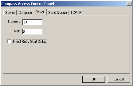
 - Click the <Add> button and locate "Compass Access Control Panel" in the list in the "Choose Driver Type" dialog. Click <OK>. The "Compass Access Control Panel" dialog appears.
- Make sure the Domain and Net correspond to the ICM Panel.

- Set up the communications as needed for your panel. In this example, the ICM is connected via a TCP/IP network. We would switch to the TCP/IP tab and add the address of the Compass panel.
- Click <OK>
- Bring the Compass Driver online by right-clicking on the Driver and selecting "Online" in the context menu.
- Connect the Digi to the ICM.
- Auto-detect the ICM. This will convert the IRM into an ICM.
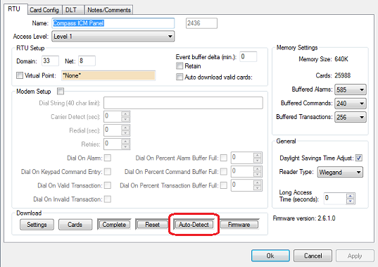
- In the Workstation, right-click on the ICM RTU and select "Properties..."
- On the "RTU" tab, click <Auto-Detect>

Intelli-Site will detect the ICM at address 8 and load the ICM firmware. When you hear the download complete message, you may move on to the next step.
NOTE: While it is not strictly necessary, it is helpful to "virtualize" the RTU while the IOM Slave Panels are added and configured. To "virtualize" the panel, click the checkbox next to the "Virtual Point" field. This will reduce the traffic on the network while the other panels are being configured.
Setup the IOM Slave Panel(s)
- In the Workstation, add the IOM Slave Panel in the same manner as adding the ICM but select "Compass IOM Slave Panel". Be sure you are choosing the Slave panel.
- Open the "Properties..." for IOM Slave Panel. Set the Net to the correct address on the slave chain. Remember the slave addresses start and the ICM address + 1. If the ICM's address is 8, then the first IOM Slave Panel's address is 9. Click <Apply> to commit the address change.
- Move the Digi to the target IOM Slave Panel.
- Click <Auto-Detect>.
- When you hear the download complete message, repeat these steps for the next IOM Slave Panel in the chain. Repeat until all of the slaves for this ICM are configured.
NOTE: While it is not strictly necessary, it is helpful to "virtualize" the RTU while the IOM Slave Panels are added and configured. To "virtualize" the panel, click the checkbox next to the "Virtual Point" field. This will reduce the traffic on the network while the other panels are being configured
When the download to the IOM Slave Panel is complete, the panel will drop offline and the DriverService will display ![]() . This is expected. The IOM Slave Panel is now configured to communicate with the ICM once it is connected via the RCO communications board.
. This is expected. The IOM Slave Panel is now configured to communicate with the ICM once it is connected via the RCO communications board.
Properly connect the IRM and IOM Slave Panel(s)
Once all of the IOM Slave Panels are configured, return the Digi to the ICM and connect all of the IOM Slave Panels to the ICM using the RCO Communications board making sure to connect them in the correct order.
NOTE: If the RTUs were "virtualized", please remember to "unvirtualize" them at this time.
Now we can define the access levels for the outputs on the IOM Slave Panels and assign them to card holders.
Just like Readers on Doors fire relays to open the door, the ICM must be configured to fire the correct output relay. In fact, more than one relay can fire at a time. Which outputs fire is defined in an RCO Group for the ICM. Each ICM will have its own set of RCO groups. An RCO group is not directly assigned to a cardholder. The RCO group is associated with an Access Level which is assigned to cardholders via Access Groups and Access Sets. The RCO group tells the Reader which outputs to fire when a valid card read occurs. To define an RCO group we need to have:
- An ICM Reader for an elevator
- An Access Level (which requires a Time Code)
- A list of Outputs that will be triggered on a valid read. These outputs provide access to the various floors.
When a cardholder who has been assigned an Access Set that contains the specified Access Level scans his/her card during the appropriate time period, he/she has access to the floors associated with the outputs in the list defined in the RCO group. In reality, this is exactly the same behavior for an IRM or ICM. The only difference is to what the outputs are wired: a door or a floor.
Before an RCO Group can be created, any time codes and access levels associated must be defined. For example, some elevator passengers have access to the top two floors during regular business hours. We need a time code for "Regular Business Hours" and an Access Level for the ICM for the "Regular Business Hours" so the ICM knows what Access Level to look for when a card is read. The place to add Time Codes, Access Levels, and RCO Groups can be found by expanding the ICM in the tree.
- Add time codes to the ICM as needed.
- Create access levels as appropriate for your site.
- Create RCO groups:
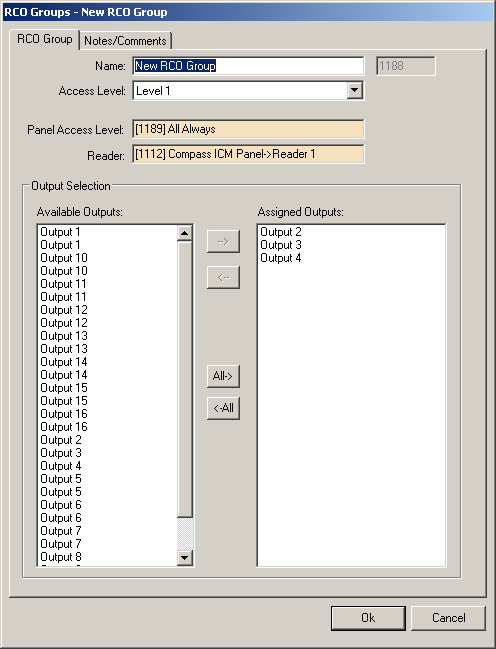
- Right-click on "RCO Groups" under the ICM in the tree and select "Add Node and Edit...".
- Drag and drop the specific Access Level into the "Panel Access Level:" drop box
- Drag and drop the correct ICM Panel Reader into the "Reader:" drop box
- Select the target outputs in the "Available Outputs:" list and move them to the "Assigned Outputs:" list.

- Click <Ok>
NOTE: As always, it is good practice to name objects logically so that you know exactly which object it is, what it controls and where it is located on your site. Name the RCO Group appropriately and name the outputs appropriately as well. To name the outputs you must bring up the Properties... for each of them. We suggest you name them to match the cab and floor.
Grant Card Holders Access:
Now that the ICM and IOMs are configured and the RCO Groups have been defined, it is time to grant card holders access to the elevator cars and floors. A card holder is assigned and Access Set. An Access Set contains one or more Access Groups. Access Groups combine one or more Access Levels. Therefore we need to:
- Create an Access Group with the Panel Access Level that you used above in the RCO Group.
- Create an Access Set that contains this Access Group
- Assign that Access Set to card holders in Card Management.
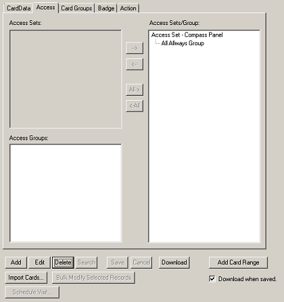
- Locate the desired cardholder.
- Click <Edit>
- Switch to the Access tab.
- Highlight the desired Access Set and move it to the the list box on the right.

- Click <Save>
Congratulations, you have configured your IRM and IOM Slave Panels to control an elevator and have granted card holders access.
Products
APPLIES TO
- Intelli-Site ES v.3.9
- Intelli-Site GS v.3.9
- Compass Hardware
Copyright © 2013 OSSI, LLC. All rights
reserved.
Intelli-Site®
is registered in U.S. Patent &
Trademark Office.
All other registered and unregistered
trademarks are the sole property of their
respective owners.